

|
Complete
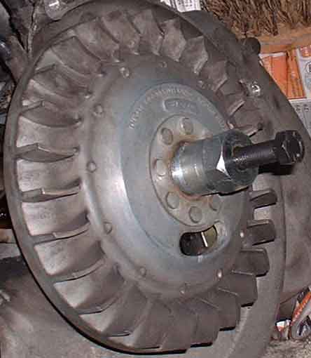
Vespa smallframe engine strip down and rebuild. The flywheel on a vespa serves four purposes. Firstly like any flywheel it keeps the engine turning on the idle strokes, secondly it directs air to cool the cylinder, and thirdly, in conjunction with the stator plate, it generates electricity to power the lights and horn and spark. Finally it also provides the ignition timing. So obviously you want to be quite careful when removing it. To actually remove it you need to remove the flywheel cover if you have not already done so, which will allow you to unscrew the nut in the centre. You will almost certainly need to prevent the flywheel from moving when you do this. You can use the Vespa flywheel holding tool or you can make something similar. Basically you need a fairly strong piece of metal that screws into one or two of the holes vacated by the flywheel cover and jams against the fins on the flywheel, preventing it from turning. On some early smallframes there is a circlip which should be left in place. As you undo the nut it pushes against the circlip and forces the flywheel up the shaft. On most others you will need to use the Vespa smallframe flywheel puller. This screws into the threads in the centre of the flywheel and you tighten a bolt in the centre to put pressure on the shaft. A few taps with a hammer on this bolt may well be necessary to loosen the flywheel so that you can remove it.
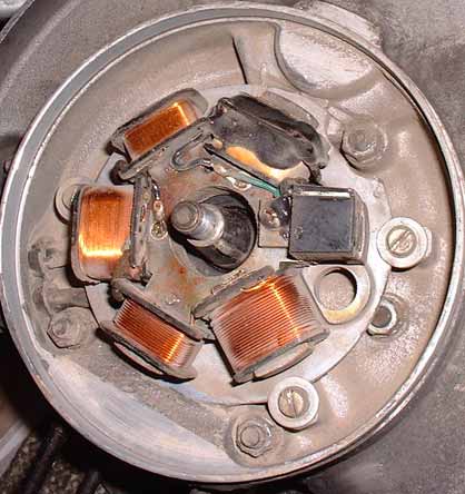
There is quite a strong magnetic bond to the stator (which is used to generate electricity) so be careful removing the flywheel. When you remove it make sure that the woodruff key that locates it is not lost. You'll notice that the flywheel has six magnets around the inside separated by grooves. These pass over the various coils and generate the electricity. If you look at the stator you should notice a raised mark cast into the stator plate that (on a stock motor) lines up with a similar mark cast into the engine case. This is the timing mark and the stator will be lined up with this at the factory to save them the bother of timing the engine properly when churning them out by the thousand. It's close enough, but you may find that the marks don't quite line up in which case the engine may well have been timed accurately later. You may also find that the marks don't line up at all. This may mean that the engine is timed incorrectly, but may well also mean that the original ignition timing is no longer appropriate - usually because the engine is in some way no longer stock. Changes of wiring harness and stator, cylinder kits, cylinders from other models etc could all mean timing changes or at least that the marks won't line up.
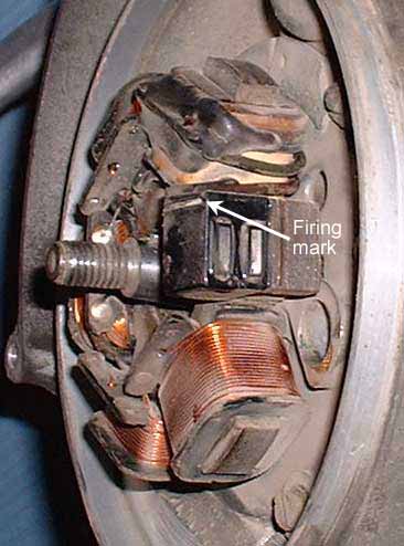
On the ET3 engine pictured here you can see the electronic ignition contact. When this lines up with a point on the inside of they flywheel where the magnets either side of one of the grooves overlap each other. When this point passes the contact a signal is sent to the CDI box which then sends the spark voltage along the HT lead. You can see a white line on the top of the contact. If you look at the flywheel there is a hole with a rubber bung in. Remove this bung to reveal two small marks in the flywheel. When these marks line up with the white line on the contact (viewable through the hole) the spark plug will fire. On a points ignition model there is a pad that bumps against the points to send the spark.
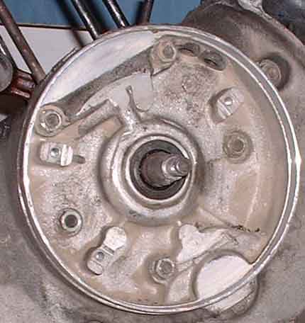
After noting where the stator lines up you can loosen the three bolts that hold it in place. Note that there is a slot which allows the stator to be rotated about ten degrees in either direction to adjust the timing. Remove the bolts to remove the stator plate, carefully feeding the wires through from the outside of the engine. Now you can see the flywheel-side oil seal. This can be removed and replaced with a new one without needing to remove the engine from the bike. Of course if you're taking the engine apart you should replace it as a matter of course. It is removed from the outside of the engine.
|
Back to Tech Index
Previous - Removing the clutch